Monday, June 13, 2011

Using the Arduino's ICSP: Workaround for a Fried ATmel8U2

As long as you didn't damage the micro-controller, you still might be able to use your Arduino board. This post assumes that you have the same problem that I do, a busted USB chip.

I searched all over the internet for a solution for the Arduino Mega 2560, but never found a definitive answer. After much trail and error, I think I may have found a sure way to upload sketches to your Arduino Mega 2560 without a functioning USB chip. This problem is a lot more trivial for the other boards, but the ATmega2560 chip causes a lot of new problems due to its large memory size. The solutions that worked for the other boards don't apply to the Arduino Mega 2560 because its flash memory is larger than 128kb and therefore uses a different uploading protocol.

You might have wondered why I didn't include a video in the last blog post on motor drivers... probably not. Long story short, I fried the ATmel8U2 chip on my Arduino Mega board. The ATmel8U2 chip replaced the FTDI chip from the earlier Arduino models and controls the USB-to-serial communications. Without this chip you can't use the USB cable to upload sketches, but thankfully there is an alternative way to program your Arduino.

This 6-pin header is where you'll connect your AVR programmer
If you've ever worked with an ATmega chip before, you might have an AVR programmer already lying around that you can use. I am a PIC man, so I did not and had to order one. Before you decide to use the AVR programmer you already have or order a new one, make sure it is actually compatable with the 2560.

The Arduino Mega 2560 is the first Arduino to have more than 128kb of flash memory and has to use a different protocol for programming. You cannot just use any AVR Programmer, you have to make sure that it is compatible with the ATmega2560 chip. The USBtinyISP is a nice programmer you could probably build yourself that can program the ATmega328 and 168. But, it is unable to handle any chip with more than 128kb of memory. If you have a Arduino Mega 2560, make sure that the AVR programmer you buy is not a USBtiny clone.

You could buy the official ATmel AVRISP mkII programmer for $34 from their website, this is guaranteed to be compatible with the 2560. I purchased an AVRISP mkII clone from Pololu, the Pololu USB AVR Programmer for $19.95. It comes with a 6-pin ISP programming cable and a USB-mini cable.

http://www.pololu.com/catalog/product/1300

Pololu has a User Guide to help you set-up your programmer and provides downloads for the drivers and AVR Programming software.

If you have any board other than the Mega 2560 (less than 128kb of flash memory), there is a way to set the Arduino IDE to use the ISP programmer instead of the USB by editing the boards.txt file and changing the upload method. The Arduino IDE uses avrdude behind the scenes to upload your sketch and has AVRISP compatibility. This method didn't work for my board and programmer, so I'm not going to go into details. Google is your friend.

After many wasted hours messing with avrdude, I found a way to upload sketches written in the Arduino IDE with the Pololu USB AVR programmer using AVR Studio 4.

Start a new file in AVR Studio for your Atmega 2560 chip. Plug in your AVR programmer and your Arduino Board. You will need to power both the programmer and the Arduino board separately, the programmer doesn't provide power for the Arduino. Connect the 6-pin ISP cable to your Arduino's ISP header.

Goto Tools>Program AVR>Connect...


Select AVRISP as your platform and whichever COM port your programmer is connected to. Auto may or may not work.


In the Main Tab, set your device to the ATmega2560 and your ISP frequency to 1.843 MHz (not sure if the freq change is necessary, but it works for me). If you click the Read Signature button, it will check the pin connections and make sure it's plugged in correctly.


If you look inside of the boards.txt file located in your Arduino directory, you can find the Fuse and Lock Bits settings for the ATmega2560. Double check the Fuse Tab to make sure that they match with the ones above, I didn't have to fix anything here. If not, change them and hit the program button.


Under the Lock Bits Tab, you will need to edit the values. The default value should be 0xFF, but the required value in the boards.txt file is 0x0F. If you try to type in 0x0F, it will change to 0xCF. I just left it at 0xCF and clicked the Program button. If it gives you a verification error, Uncheck the Verify after programming box and re-click the Program button.


Depending on what happened to your board, you may need to re-burn your bootloader onto your chip. Locate the hex file in your Arduino folder:
arduino-0022\hardware\arduino\bootloaders\stk500v2\stk500boot_v2_mega2560.hex
Load it into the Flash section of the Program Tab, but don't click the button just yet.


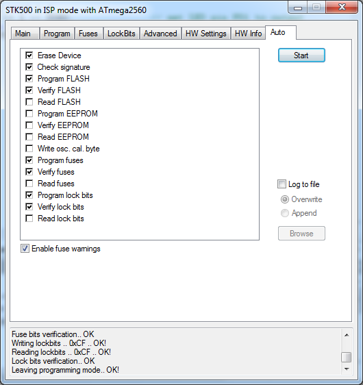
Goto the Auto Tab and check the following boxes and click the Start Button. If everything was set correctly, you should now have the bootloader freshly installed onto your Arduino board. If you cannot upload the bootloader onto your chip, try updating the firmware on the Pololu USB AVR Programmer. Check the User Guide for details. If it still won't program, check to see if anything beside the USB chip was fried. Your Arduino may be more damaged than you thought.


As of right now, there is no easy way to convert your sketches into .hex files. When you compile your sketches in the Arduino IDE, it creates a temporary hex file that you will need to locate in your computer's TEMP folder. I am using Windows 7 so this might not apply to you. KEEP THE ARDUINO IDE PROGRAM OPEN WHILE YOU LOCATE THE HEX FILE. Open up the sketch that you want to upload and compile it. Go to your temp folder(you will need to have hidden folders viewable):
C:\Users\"Your Name"\AppData\Local\Temp
There will be a folder called "build" followed by a large string of random numbers. Inside the folder will be your sketch's hex file. It's easier to find if you have file extensions viewable. I suggest moving this file to your desktop or another folder as it will be deleted once you close the IDE program.


Go to the Program Tab and now upload the sketch's hex file in the flash section.


Finally, go back to the Auto Tab and click the Start button. Huzzah! As long as there were no errors your sketch should now be uploaded to your Arduino Mega 2560.

Manly tears were shed

It may not look like much to you, but after trying everything to fix this board for the past week... reading every single forum post... clicking on every single Google link... Getting that LED to finally blink was quite the accomplishment.

After I get some well deserved rest, I'll be sure to get back to updating the blag regularly. We almost lost the Arduino there, but the blag must go on.

Monday, June 06, 2011

Motor Drivers: 1A Dual TB6612FNG Part 1

It's time to wipe the Cheetos dust from your mouth because we're gunna get that Arduino rollin' tonight.

Maybe later...

Unlike a servo which has separate wires for the control signal and voltage supply, DC motors only have two terminals available. Try plugging one of those in to a digital output pin and you'll fry the Arduino. Plug them into the 5V output and GND pins and the wheels are just going to spin and you'll have no control over the speed or direction. So, what do we with these two you ask?

Your motors are going to require more current than any micro-controller can safely handle, so were going to need some extra circuitry for a motor controller. You can use an IC H-bridge such as the L293D ($2.95 at Jameco) for a motor driver if your motors do not have a peak current over 600mA. The L293D allows you to either control two motors bidirectionally or four motors in a single direction. Each output pin already has built in back-EMF protection for when you reverse directions or suddenly stop the motor and it even has a separate input for the power supply and logic voltage. But, if you are planning on using any larger motors whose current exceeds 600mA  you will need to use another motor driver or you will melt the chip. I've read that you can just piggyback and solder two chips on top of one another to double the max current, but there is a cleaner alternative if you're willing to spend an extra $3.

The motor driver I'll be using for my robot buddy is a breakout board for the Toshiba TB6612FNG chip from Sparkfun. http://www.sparkfun.com/products/9457

This bugger is a lot smaller than you'd think
I really need to start using a camera to take pictures. I assure you there's text printed on it.
Size comparison against two 16-pin IC

This board can control two motors requiring a supply voltage up to 15V and constant current of 1.2A with a peak current up to 3.2A. There is also a separate voltage supply for the motors and logic. This chip allows you to not only control the direction of each motor, but you can also control the speed of your motors using the PWM input pins. Neat! Below is a table from the chip's datasheet showing how to control the direction of your motor.

Courtesy of Toshiba's TB6612FNG Data sheet
So, you already got two motors and a driver? Well then, let's get coding.

Being the environmentally responsible person that I am, I built a test platform for our motor driver using an old Sparkfun box I had lying around. It ain't pretty, but it will do for this post. Since the platform only has two wheels, I'll be using a nub thingy(guitar pick) to keep it balanced for the time being until I get some sort of castor wheel. If it weren't 4am, I'd go to the hardware store. Maybe I'll get one tomorrow if I'm not feeling overwhelmingly lazy.

Inside sits two geared DC motors.
Just to test the code, right?
The motor driver is well labeled, so the wiring is pretty self explanatory. Here's a quick sketch I wrote that allows you to control the speed and direction of your motors. It includes functions for driving forward and reverse, turning, and braking. Check the code's define section for how I wired it. The logic supply voltage can be connected to the Arduino's 5V supply. I would highly suggest having a separate battery pack for the motor voltage supply. You can control your supply voltage and you don't risk damaging the Arduino.

Depending on how you have your motors set-up, this code might not work as intended for you. All you need to do to fix this is change the #define values for the incorrect directions.

//  Noah Stahl
//  6/5/2011
//  http://arduinomega.blogspot.com
//  Arduino Mega 2560
//This sketch is used to control the TB6612FNG Motor Driver.
//The Motor Driver is controlling two bidirectional DC Motors, A and B.
//There are four states for each motor in this code: STANDBY, BRAKE, CW, CCW.
//The speed of the motors can be controlled through PWM. 0 for stopped and
//255 for full-speed.

//!!!READ-ME!!!
//Depending on the placement and wiring of your motors, this code may not work
//as intended on your project. You can fix any of the wrong directions by
//changing the FORWARD, REVERSE, RIGHT, and LEFT define values below.
//You will also have to do a little experimenting to determine a good delay
//value for turning. This value is going to change depending on your motor speed,
//torque, surface material, battery voltage, and a whole bunch of other variables
//that you will probably be unable to account for. Just use a good guess.

#define PWMA 2
#define AIN1 53
#define AIN2 52
#define BIN1 51
#define BIN2 50
#define PWMB 3
#define STBY 49
#define motor_A 0
#define motor_B 1
#define FORWARD 1
#define REVERSE 0
#define RIGHT 1
#define LEFT 0

void setup()
{
  pinMode(PWMA,OUTPUT);
  pinMode(AIN1,OUTPUT);
  pinMode(AIN2,OUTPUT);
  pinMode(PWMB,OUTPUT);
  pinMode(BIN1,OUTPUT);
  pinMode(BIN2,OUTPUT);
  pinMode(STBY,OUTPUT);
 
  motor_standby(false);        //Must set STBY pin to HIGH in order to move
}

void loop()
{
  motor_brake();               //STOP for 1s
  delay(1000);
  motor_drive(FORWARD, 255);   //Move FORWARD at full speed for 1s
  delay(1000);
  motor_brake();               //STOP for 1s
  delay(1000);
  motor_drive(REVERSE, 150);   //REVERSE at about half-speed for 1s
  delay(1000);
  motor_brake();               //STOP for 1s
  delay(1000);
  motor_turn(RIGHT, 255, 255); //Spin RIGHT for 0.5s
  delay(500);
}

//Turns off the outputs of the Motor Driver when true
void motor_standby(char standby)
{
  if (standby == true) digitalWrite(STBY,LOW);
  else digitalWrite(STBY,HIGH);
}

//Stops the motors from spinning and locks the wheels
void motor_brake()
{
  digitalWrite(AIN1,1);
  digitalWrite(AIN2,1);
  digitalWrite(PWMA,LOW);
  digitalWrite(BIN1,1);
  digitalWrite(BIN2,1);
  digitalWrite(PWMB,LOW);
}

//Controls the direction the motors turn, speed from 0(off) to 255(full speed)
void motor_drive(char direction, unsigned char speed)
{
  if (direction == FORWARD)
  {
    motor_control(motor_A, FORWARD, speed);
    motor_control(motor_B, FORWARD, speed);
  }
  else
  {
    motor_control(motor_A, REVERSE, speed);
    motor_control(motor_B, REVERSE, speed);
  }
}

//You can control the turn radius by specifying the speed of each motor
//Set both to 255 for it to spin in place
void motor_turn(char direction, unsigned char speed_A, unsigned char speed_B )
{
  if (direction == RIGHT)
  {
    motor_control(motor_A, REVERSE, speed_A);
    motor_control(motor_B, FORWARD, speed_B);
  }
  else
  {
    motor_control(motor_A, FORWARD, speed_A);
    motor_control(motor_B, REVERSE, speed_B);
  }
}

void motor_control(char motor, char direction, unsigned char speed)
{
  if (motor == motor_A)
  {
    if (direction == FORWARD)
    {
      digitalWrite(AIN1,HIGH);
      digitalWrite(AIN2,LOW);
    }
    else
    {
      digitalWrite(AIN1,LOW);
      digitalWrite(AIN2,HIGH);
    }
    analogWrite(PWMA,speed);
  }
  else
  {
    if (direction == FORWARD)  //Notice how the direction is reversed for motor_B
    {                          //This is because they are placed on opposite sides so
      digitalWrite(BIN1,LOW);  //to go FORWARD, motor_A spins CW and motor_B spins CCW
      digitalWrite(BIN2,HIGH);
    }
    else
    {
      digitalWrite(BIN1,HIGH);
      digitalWrite(BIN2,LOW);
    }
    analogWrite(PWMB,speed);
  }
}


I would highly suggest that you power your motors with their own battery source, perhaps a few rechargeable NiMH AA's. If you use the 5V supply from the Arduino for the motor supply voltage, you might damage the Arduino by drawing too much current. 

Once again, your mileage may vary with the code. Depending on how you have your motors set-up, this code might not work as intended for you. All you need to do to fix this is change the #define values for the incorrect directions. Also, depending on your power supply's voltage and amperage ratings, the timing delays for turning are going to be different.  Do a few test runs and figure out the optimal delay values for your project.